
Optical Rotary Joint Manufacturer Delivering Precision Fiber Optic Solutions
2026-09-03
Signal integrity across a rotating interface is where many motion systems fail—especially when the data is optical. That's exactly the challenge MOFLON tackles as an optical rotary joint manufacturer delivering precision fiber optic solutions. From wind turbine nacelles to robotic joints that can't afford a single dropped pulse, MOFLON's rotary joints keep light paths stable under rotation. In this post, we break down what separates reliable optical rotary joints from the rest and how MOFLON builds that reliability into every unit.
Rotating Light Without Losing a Single Photon
Turning a beam of light usually costs you brightness. A half-wave plate can rotate polarization, but any imperfection scatters a few photons. This problem becomes stark when you deal with single photons or delicate quantum states, where losing even one particle breaks the whole experiment.
The trick is to rotate the light's spatial structure without touching its intensity. By using specially patterned liquid-crystal devices or carefully shaped metasurfaces, the beam's phase and polarization twist together. The photons stay in the same mode count, so none are absorbed or reflected away.
In practice, this means a vortex beam can spin from horizontal to vertical or gain orbital angular momentum while the total photon number stays constant. Researchers test this by sending weak pulses through the device and checking that the input and output counts match to within detector noise. It is a quiet but crucial advance for optical computing and quantum communication, where every photon has to arrive.
The Tolerance Story Behind Every Fiber Optic Joint
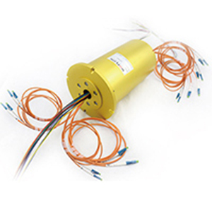
Most people see a fiber optic joint as a simple plug-and-socket affair, but the real conversation happens at a scale smaller than a human hair. A single-mode core is only nine microns wide, so the tolerance that matters is not millimeters or even tenths of a millimeter—it is the lateral offset between two cores measured in fractions of a micron. Ceramic ferrules are ground to hold that core within a bore that itself has a couple of microns of clearance. Alignment sleeves gently press the ferrules together, but even the roundness of the ferrule tip, the angle of the polish, and the concentricity of the fiber inside the ferrule all decide whether photons cross the gap or scatter into the cladding.
That stacking of tolerances is where most loss accumulates. A ferrule with an eccentric bore, a fiber that sits off-center inside its coating, or a polished end face with an apex offset can each add a small penalty. Measured individually, none looks dramatic; combined across a connector pair, they can turn a nominal 0.1 dB joint into a 0.5 dB problem. Manufacturers fight this by sorting ferrules, measuring insertion loss in every direction, and tuning the radius of the end face so the cores touch before the surrounding ceramic does. The tolerance chain does not stop at the glass, either—spring force, mating adapter wear, and even the durometer of the alignment sleeve all play a role.
In the field, the story becomes even less forgiving. A single dust particle on the end face can be wider than the core itself, so a quick wipe or inspection is not optional. Temperature cycles expand and contract connector housings by a few microns, shifting the alignment you carefully bought. Repeated matings wear the ferrule surface and gradually change the polish geometry. This is why a well-made joint is less about hitting a perfect number on a test report and more about understanding that tolerance is a living, cumulative thing—one that gets decided again every time two fiber ends meet.
Where Mechanical Rotation Meets Optical Stability
The marriage of mechanical rotation and optical stability rarely gets the attention it deserves. In most imaging or sensing setups, the spinning element introduces jitter, wobble, and drift that degrade the signal. But when the rotating stage is built with precision bearings, thermally matched materials, and a feedback loop that anticipates micro-slip, the optical path stays locked. The light sees a stationary world even as the housing turns at hundreds of RPM. That paradox drives a niche branch of engineering where the tiniest bearing eccentricity becomes visible in a fringe pattern or a beam centroid.
Designers working at this intersection often discover that optical stability is not just about tightening tolerances. It involves distributing mass asymmetrically to counter centrifugal flex, using air bearings to avoid metal-to-metal chatter, and embedding accelerometers that correct tilt faster than a single rotation. The result is a system where the rotating axis and the optical axis become indistinguishable. You can put a camera on a spinning arm, point it at a fixed target, and the image remains as crisp as if the arm were bolted to granite.
What makes this field compelling is the absence of a single recipe. Every solution depends on speed range, payload stiffness, and wavelength sensitivity. Some teams rely on passive balancing with tuned elastomers; others use active magnetic preload that changes with thermal expansion. The constant is an obsession with the interface between moving metal and still photons. That interface, once tamed, enables gyro-stabilized telescopes, rotary lidar with sub-pixel registration, and optical coherence tomography probes that spin inside arteries without losing focus.
Custom Geometries, Consistent Optical Performance
Achieving a truly custom optical component often starts with geometry that doesn't exist in any catalog. Freeform surfaces, off-axis paraboloids, or asymmetric lens profiles can reshape how light is directed, but the real challenge is keeping the optical behavior identical from the first prototype to the thousandth unit. That's where precise tooling control and interferometric verification come in — mapping surface deviation at every stage so the custom shape never drifts from its intended wavefront.
Rather than treating geometry and performance as separate goals, we integrate them during the design phase. Every curve is simulated not just for its ideal form, but for its sensitivity to manufacturing tolerances. This means a steeply aspheric mirror or a lens with an unusual edge contour can be produced repeatedly with the same modulation transfer function and scatter characteristics. The result is a component that fits your mechanical envelope without forcing you to revalidate the optical system.
In practice, that consistency removes a major bottleneck. You can prototype a housing around the exact optical surface you need, then scale to production knowing the imaging quality, focal spot size, or beam shaping profile will remain stable. Custom geometry becomes a reliable design variable rather than a risk factor, opening up compact and lightweight optical layouts that standard elements simply can't support.
Building Joints That Outlast the Mission
In high-cycle environments, the joint isn't just a connection—it's where stress concentrates and where small misalignments turn into failures. Designing joints that outlast the mission means moving beyond static load calculations and treating each interface as a system with its own fatigue life, wear patterns, and tolerance drift.
A joint that survives the mission isn't necessarily the strongest one; it's the one that fails gracefully. By selecting fasteners and base materials with complementary thermal expansion coefficients, and by preloading them to stay within the elastic range under peak loads, you shift the failure point away from sudden fracture toward detectable yield. That gives maintenance teams a window to act before something breaks.
The real proof is in sequenced overload testing and post-test inspections that look for fretting, galling, or microcracks around hole edges. These signs tell you whether the joint will last beyond the stated envelope—or only until the last acceptance test.
Precision Is Not a Feature—It’s the Foundation
Most teams treat precision like a switch they can flip at the end—something to bolt on once the rough edges are sanded down. But that logic collapses the moment you watch a complex system behave in ways no one predicted. Precision isn't the polish; it's the load-bearing wall. Strip it away and every downstream decision, every handoff, every assumption quietly drifts into ambiguity. The people who build durable things learn this early: you don't add exactness later, you either bake it into the first line of code, the first sketch, the first conversation, or you spend twice as long fighting the fog you created.
Think about the last time a project went sideways. Chances are the failure wasn't a dramatic collapse but a slow erosion of shared understanding—a requirement that meant one thing to engineering and another to design, a metric that was “close enough” until it wasn't. Precision acts as a forcing function. It makes hidden disagreements visible, turns vague hopes into testable claims, and gives a team permission to say “we don't actually know this yet” without pretending otherwise. That's uncomfortable, which is why many avoid it. But discomfort fades; rework doesn't.
The foundation mindset shifts what you optimize for. Instead of chasing speed by deferring clarity, you treat early exactness as an accelerant. A precise problem statement lets five people move in parallel without colliding. A precise definition of done kills the endless “but I thought you meant…” loops. The teams that look fast from the outside are rarely the ones who rush—they're the ones who spent more time making sure everyone was aiming at the same point. Precision doesn't slow you down. It removes the friction that masquerades as progress.
FAQ
A standard slip ring transmits power and electrical signals across a rotating interface using metal contacts. An optical rotary joint does the same job for light, using fiber collimators or waveguides instead of brushes. Precision versions push that further with tighter alignment tolerances, lower insertion loss, and better return loss so high-bandwidth optical signals stay clean while rotating.
It comes down to the optics and the mechanics. We use angle-polished connectors to suppress back reflections, precision bearings to keep the rotating axis stable, and collimating lenses that expand the beam across the gap so tiny misalignments don't cause large losses. The result is a rotary joint that can spin for millions of cycles without noticeable drift.
You'll find them in medical imaging systems like OCT, in wind turbines for blade pitch control, in remote-operated vehicles, and in military turrets. Anywhere a cable would twist or tangle while data needs to flow at high speed, an optical rotary joint removes that failure point.
Look beyond the spec sheet. Ask about their in-house polishing and alignment equipment, whether they test every unit for insertion loss and return loss, and how they handle fiber strain relief. A manufacturer that can provide test reports and custom wavelength options is usually more dependable than one that sells only off-the-shelf parts.
Yes, with the right housing. Stainless steel or anodized aluminum bodies, O-ring seals, and hermetic fiber feedthroughs protect the internal optics from moisture, dust, and salt spray. Some designs are rated for IP68 or even deep-sea use, but you need to specify the pressure and temperature range up front.
More channels mean more optical paths to align in a single rotating assembly, which increases complexity and often the package size. Multi-channel joints can carry separate bidirectional data streams or combine single-mode and multi-mode fibers in one unit, but cross-talk and mechanical balance must be managed carefully.
Customization can cover fiber type, wavelength range, connector style, housing material, mounting flange, and even integrated electrical slip rings for hybrid power and data. We usually start with the customer's rotational speed, environmental conditions, and channel count, then design the optics and mechanics around those limits.
Conclusion
At the heart of every optical rotary joint we manufacture lies a simple but uncompromising promise: rotate light without losing a single photon. This is not a marketing slogan—it is the tolerance story behind every fiber optic joint we build. From the first drawing to the final polish, each component is machined and assembled to sub-micron precision, because even a fraction of a degree of misalignment can scatter the very signal you depend on. Where mechanical rotation meets optical stability, we engineer interfaces that allow continuous 360-degree motion while keeping insertion loss flat and return loss high, regardless of speed, torque, or environmental stress. Our joints do not merely spin; they carry data through the turn without a whisper of degradation.
Precision is not a feature we add at the end—it is the foundation poured before the first bearing is seated. That is why we embrace custom geometries with consistent optical performance, tailoring fiber counts, wavelengths, and channel layouts to your exact mission profile. Whether your platform is a surgical robot, a wind turbine slip ring replacement, or a deep-space gimbal, we build joints that outlast the mission itself. Every channel is tested under load, every collimator aligned under interferometry, and every unit serialized with its own test report. The result is not another catalog part. It is a rotating optical interface that disappears into your system—quietly, reliably, and with the kind of precision that cannot be copied by anyone who treats optics as an afterthought.
Contact Us
Contact Person: Xiangpin Li
Email: [email protected]
Tel/WhatsApp: 86 186 1706 8578
Website: https://www.moflon.com