
Feeding System Fabrication: A Guide to Building Reliable Automated Feeders
2026-10-13
An automated feeder only earns its place on the line when it runs unattended for months, not hours. Yet most fabrication guides stop at basic concepts, leaving you to discover through costly downtime which tolerances matter, which welds crack, and which controls drift. This guide changes that. We’ll go inside the build process for reliable feeding systems—covering everything from frame rigidity and track alignment to sensor placement and fail-safe logic. Along the way, Fanchang Machinery shares field-tested techniques that separate robust feeders from those that merely look good in a CAD model. If you’ve ever wondered why some feeders thrive on the floor while others become maintenance nightmares, the answer lies in the details ahead.
Material Choices That Keep Feeders Running Past Their Warranty
The difference between a feeder that dies six months in and one that hums along for years often comes down to what it's made of. Stainless steel components resist the rust that eventually eats through cheaper alloys, especially in humid or coastal environments. Meanwhile, food-grade plastics with a high molecular weight shrug off the constant friction from seed and shell, avoiding the micro-cracks that let moisture creep into motor housings.
It's not just about the obvious parts. Gaskets and seals made from silicone rather than rubber keep their flex after hundreds of temperature swings, so dust and fine particles stay out of the gearbox. And when the sun beats down day after day, UV-stabilized polymers retain their strength instead of turning brittle and snapping at a mounting point. These are the quiet material upgrades that let a feeder outlast its warranty by a wide margin.
You don't need to be an engineer to spot the difference. Run a finger over the edges, check for any unfinished metal, and give the hopper a gentle flex in the store. If it feels like it might fight back after a season of weather, it probably will. Feeders built from robust, purpose-selected materials rarely make a fuss—they just keep spinning, clicking, and dropping feed long after the paperwork expires.
Geometry and Tolerance Decisions That Prevent Most Jams
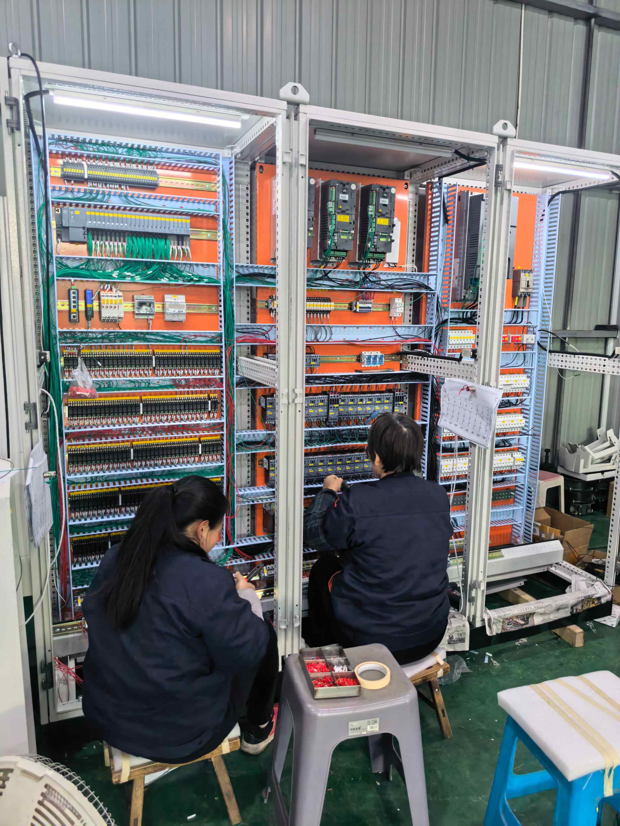
Most jams in sheet-fed mechanisms don't stem from a single catastrophic flaw but from a slow accumulation of small geometric mismatches. A subtle ledge at a guide joint, a radius that is slightly too tight for the stiffest media in the batch, or a parallelism error across a feed path can turn an occasional hesitation into a repeat stoppage. Designers who focus on the exact contour where media first contacts a guide or roller often eliminate the majority of field failures before any tolerance stack-up analysis is needed.
Tolerance decisions work best when they are tied to measurable media variation rather than generic drawing defaults. For instance, if paper weight can vary from 60 to 120 gsm, the gap between a feed roller and separator pad should reference the thickest sheet plus a small clearance, not a nominal midpoint. Similarly, guiding surfaces that are angled more than twenty degrees from the feed direction benefit from a lead-in radius at least three times larger than the maximum expected curl height. Keeping parallelism within +/-0.15 mm across a 300 mm wide path is often sufficient to prevent skew-induced buckling, but only when the side guides themselves are straight within half that value.
Another geometric choice that prevents most jams is eliminating sharp internal corners where media changes direction. Replacing a square edge with a blended radius of 4–6 mm at a turnaround or flap gate reduces the chance that a slightly curled leading edge will catch. Chamfers on mating plastic parts should be at least 0.5 mm deep and 15 degrees from the feed plane, because smaller chamfers disappear under normal injection molding variation. Specifying these features as functional tolerances rather than cosmetic notes turns the geometry into an active safeguard, letting even loose part tolerances coexist without creating jam points.
Actuator and Sensor Pairings That Eliminate Guesswork
Instead of hoping that an actuator behaves as commanded, a well-chosen sensor pairing turns every movement into a measured fact. For example, a brushless motor matched with a low-latency shaft encoder can verify that each commutation step actually produced the expected angular change. When the sensor is mounted close to the load rather than the motor body, backlash and flex stop being hidden variables. The system stops guessing because the feedback path aligns with the physical output that matters.
The real work is picking sensor types that catch the specific failure modes an actuator can drift into. A pneumatic cylinder paired with a linear position sensor and a downstream pressure transducer eliminates the old argument about whether the valve shifted or the load changed. Each actuator gets its own independent truth source, so a disagreement between commanded and actual state becomes a diagnosable event instead of a mysterious fault. This pairing logic also helps avoid over-instrumentation: you don't need a full inertial measurement unit when a single resolver and a current sense resistor can tell you the same story.
Over time, these tight pairings flatten the debugging curve. When an axis stalls, you can immediately see whether torque rose before position stopped changing, or whether the commanded signal never reached the driver. That removes the guesswork from both design and field support, because the system's own data points to the offending element. Rather than adding complexity, the right actuator-sensor combination creates a self-validating loop that keeps uncertainty out of routine operation.
Assembly Sequences That Turn Drawings into Dependable Hardware
Every reliable machine starts as a flat drawing, but the path from paper to working hardware is defined by assembly sequences that respect real-world fit, tolerance stacking, and human hands. The best sequences don't just list parts—they choreograph torque values, access windows, and the order in which fasteners reach their final tension. A bracket bolted before its mating surface is aligned can lock in a warp that no amount of final tightening will fix. Skilled builders learn to read a drawing as a map of dependencies, not a bill of materials, and they sequence each step so that every component finds its reference surface before it is constrained.
What makes an assembly sequence dependable is its sensitivity to the unnoticed moments: the half-turn of a screw that relieves a bind, the deliberate delay in tightening a group of bolts until all are started by hand, the choice to install a shaft from the bearing's chamfered side rather than forcing it. These are not written in the title block, yet they decide whether the hardware runs true or fights its own alignment. A good sequence also anticipates removal—the technician who must replace a seal behind a press-fit gear will curse the designer who placed a retaining ring where no puller can reach. Dependability is a two-way street: the hardware must assemble without heroics and come apart without destruction.
In practice, dependable assembly sequences emerge from iterative build feedback. The first prototype might follow the drawing's logical order, but the third and fourth reveal that installing the wiring harness before the lower panel saves pinched insulation, or that leaving one diagonal brace loose until the end lets the frame settle square. These refinements rarely change the part geometry; they change the order of operations, and that order becomes a silent spec. When a sequence is finally written down—taped to the bench or embedded in a work instruction—it carries the weight of every stripped thread and discovered interference. That is how a drawing becomes hardware you can count on: not by magic, but by a sequence that has already survived its own mistakes.
Field Testing Tricks That Expose Weak Points Early
Real conditions beat lab notes almost every time. Instead of waiting for a finished build, I take a rough prototype into the field within days of it working. The goal isn't to prove it survives—it's to find out where it quietly gives up. Mud, uneven ground, ungloved hands, bad lighting: those small frictions expose design choices that look fine on a screen but feel wrong in practice.
One trick is to hand the item to someone who has never seen it before and say nothing. Watch where they pause, what they try to force, which button they miss completely. Those hesitations are weak points you'll never catch yourself because you've already learned the workaround. Write down every confused look; later, that list becomes your fix list.
Another approach is to deliberately push one variable past its rated limit while everything else stays normal. Run the tool with a nearly dead battery, use it in direct sun after it's been in a cold trunk, overload the clip by a few pounds. Don't wait for the warranty test—break it now, when a cracked hinge or a stuck latch costs you an afternoon instead of a recall.
Designing Access Panels for Repair Without Line Shutdowns
Access panels intended for live-line maintenance start with field observation, not just CAD layout. Walk down the actual pipe rack or duct run and mark every flange, valve stem, drain, and instrument tap that might need a wrench during operation. The panel opening should give a technician enough room to swing a torque wrench or pull a long thermowell without leaning across a hot surface or reaching past a pressure boundary. A common mistake is sizing the opening for the component alone; add at least 150 mm of clear working space on each side, and more if the repair involves lifting a heavy actuator or blind flange.
Panel closure details matter as much as the opening. Where the line remains pressurized or hot, specify quick-release fasteners that do not require two hands or a tool that can fall into the process area. Hinged doors should swing away from the operator, not across the body, and include a hold-open latch. For insulated or jacketed lines, design the panel so insulation can be removed in sections without cutting the weather barrier. If the panel crosses a pipe support or a structural member, consider a two-piece split design rather than a single large cover that may be impossible to remove when the line is at temperature.
Finally, test the access concept during a planned maintenance window before relying on it for emergency work. Have a crew simulate a thermowell replacement or a small valve packing adjustment while the line runs at normal pressure. Record any spot where a tool does not fit, a panel blocks a nearby gauge, or a latch is hard to reach with gloves. Those notes should drive final adjustments to panel position, hinge direction, and fastener type. A well-designed access panel should make the repair feel almost routine, not like a confined-space entry that only works on paper.
FAQ
Start by mapping out the material flow and defining the required feed rate and accuracy. Then select a feeder type—vibratory bowl, centrifugal, or screw—based on part geometry and fragility. Build a rough prototype early to observe how parts actually move, because simulation alone rarely catches jamming or orientation issues.
Vibratory bowls handle a wide range of part sizes and are easier to tune for orientation, but they can be noisy and cause surface wear on delicate parts. Centrifugal feeders are gentler and faster for high-volume, lightweight components, though they demand more precise tooling. Choose based on part fragility, throughput, and noise constraints.
Stainless steel is common for bowls due to durability and ease of cleaning, while aluminum reduces weight and cost for lighter loads. For wear-prone contact surfaces, coated tool steel or polyurethane liners extend service life. Avoid zinc-plated parts in food or medical applications where contamination risk matters.
Use a variable-frequency drive to adjust feed rate smoothly, plus a bowl level sensor to stop the hopper from overfilling or running dry. Add jam detection via motor current monitoring or optical sensors so the system can pause and reverse automatically. These features drastically cut unplanned stops.
Focus on the bowl track geometry—round sharp corners, widen choke points, and slope surfaces to prevent parts from wedging. Tune the vibration amplitude and frequency to the part's natural movement pattern. Adding air jets or a brief reverse pulse can clear stubborn bridges without a full shutdown.
Inspect and clean the bowl and tooling weekly to remove fines and debris that alter part motion. Check drive springs for fatigue and replace them as a set. Lubricate motors and bearings per schedule, but avoid lubricants near the feed track. Record vibration settings after each retune so changes can be traced.
Run a controlled batch of 500–1000 parts at varying feed rates and record jam frequency, orientation accuracy, and cycle time. Use high-speed video to spot subtle part handling issues that visual inspection misses. Then run a continuous 8-hour trial with the actual upstream and downstream equipment connected.
Over-tightening the bowl to the drive unit causes uneven vibration; use the manufacturer's specified torque. Adding too many tooling features early on restricts flexibility—start with minimal guides and add only what the part truly needs. Also, neglecting to deburr welded seams leads to part scratching and unpredictable feeding.
Conclusion
Building a reliable automated feeder demands more than bolting together off-the-shelf parts. The choice of materials sets the foundation—hardened contact surfaces and wear-resistant liners keep components sliding smoothly long after cheaper alloys would gall or pit. Equally critical are the geometric and tolerance decisions made at the drafting table. Tight clearances around the feed track and smart draft angles on hopper walls prevent most jams before they ever occur, because small inconsistencies in part size or orientation get shunted aside rather than wedged into a dead stop. Pairing the right actuator with the right sensor removes guesswork from the control loop. A stepper motor mated to a through-beam photoeye, for instance, can confirm each index motion instead of relying on open-loop timing, which drifts as the system settles.
Once the design is locked, the assembly sequence turns drawings into dependable hardware. Starting with the frame, then adding the drive unit, then the feed bowl, and finally the escapement ensures each subassembly can be checked for alignment before the next layer hides it. No amount of shop care, however, replaces field testing tricks that expose weak points early. Running the feeder with deliberately mixed part orientations, contaminated media, and voltage sag will reveal latent failure modes that a clean lab trial never touches. Finally, designing access panels for repair without line shutdowns means choosing hinge points and tool-free fasteners at the exact spots where clogs or sensor fouling are most likely. A feeder that can be cleared in ninety seconds with a hex key beats one that requires two technicians and a forklift.
Contact Us
Contact Person: Darye WANG
Email: [email protected]
Tel/WhatsApp: 86-13501017897
Website: https://www.fcntd.com/